This is the microcontroller system I used to drive my split ring telescope mount.
I show it here because I would like to get comments on this design and my plans
for further development.
I'm building a Alt-Az telescope so I have to modify the software to control
both axes for tracking.
The CPU is an Atmel AVR (Mega AVR 161). The two stepper motors are driven by two special ICs (Infineon TCA3727).
It is a modular system with three boards put into slots of a backplane.
A minimal version of this computer could fit on one small board with all of its components.
I plan to use other stepper drivers which can handle more microsteps per fullstep (Allegro 3973).
A prototype of this was already running with a smaller controller (AVR 2313).
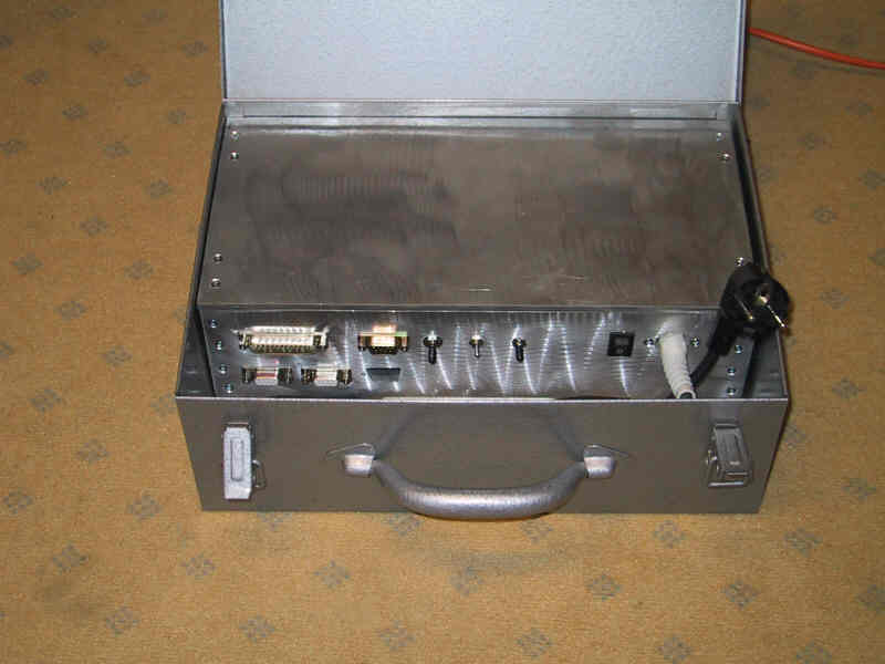
Controller box
This is the controller with its aluminum case fitted into a case for electric tools.
There are two connnectors for steppers (9 pin) and a 25 pin connector for a handbox.
The third 9 pin connector is a serial port to receive moving commands from another
computer (currently my Windows PC).
A second serial port on the CPU is currently not used. It could be used for a
more intelligent handpad instead of the 8 switches. Another possibility is to
reserve this port for firmware downloads.
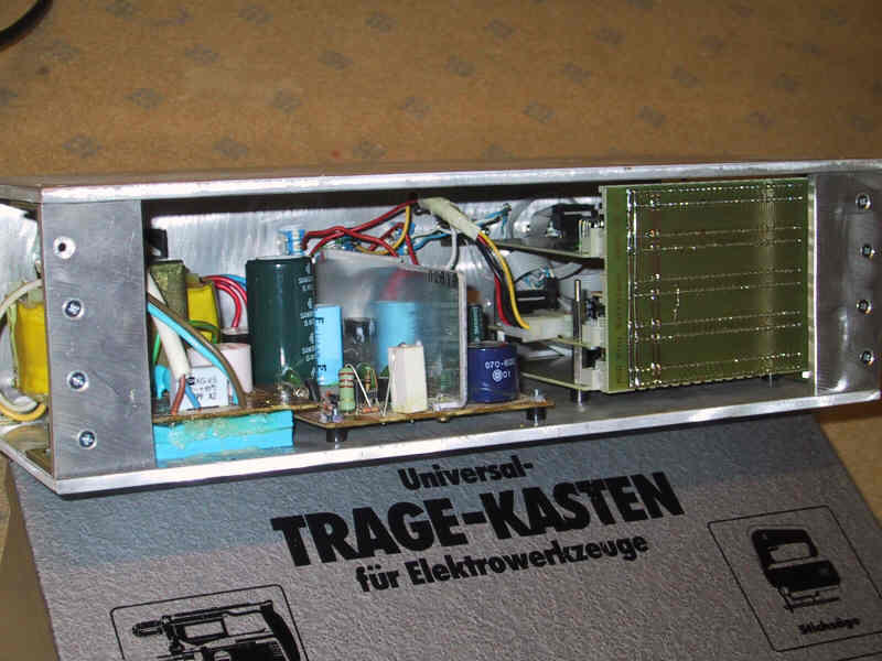
Back side of the controller box
This is the aluminum frame taken out of the box. On this picture the power
supply on the left side and the backplane of the computer (right) can be seen.
The power supply generates 24 V for the stepper ICs and 5 V for the microcontroller.
In the next revision the controller should run with one 24V supply only (car battery).
A voltage regulator will generate the 5 V on the controller board.
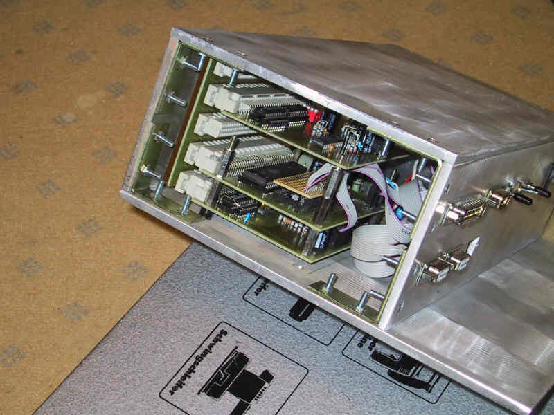
Computer system
The modular computer system consists of a CPU board (in the middle) and two stepper
control boards. They are connected by a backplane with adress and data bus. (The controller
can work in an expanded mode to access external memory.)
Some ICs on the two stepper boards handle these buses. On a minimal assembly I will take them away and the CPU
will control the stepper ICs directly by one of its I/O ports.
Then only 4 ICs are needed (and some discrete components):
1. Microcontroller: Atmel AVR mega161
2. Stepper IC 1: Allegro 3973 or 3972 (more power)
3. Stepper IC 2: Allegro ...
4. Voltage adaptor for two serial connections: Max 232
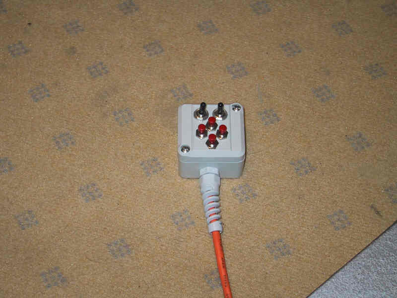
Handpad
A handpad with 8 switches is connected to one of the I/O ports of the microcontroller.
Software
The software supports the following functions:
1. Tracking in one axis (for a polar aligned mount)
2. Control via handpad: fine, medium, fast moving with ramping,
tracking speed fine adjust, linear tracking speed calculation from two (start, stop)
points and time between them
3. Monitor program for reading and writing of program variables
I used this for taking photographs with a piggypack camera.
A webcam was mounted onto the scope and a simple image analysis program
calculated guiding commands to the controller to hold a guide star centered.
Small printed circuit board
with surface mounted AVR mega128 controller and
LCD handbox, hopefully someday will do all calculations without needing a PC.