|
ATM - Martin Cibulski - 2004-06-20 |
||
| Start > Microcontroller based telescope driver IV > Hardware | ||
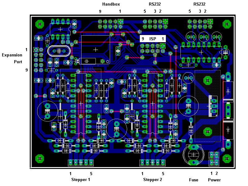
| Pin | Signal |
| 1 | Plus, 24 V |
| 2 | Minus, Ground |
| Pin | Signal |
| 1 | Motor coil 1, plus |
| 2 | Motor coil 1, minus |
| 3 | Motor coil 2, minus |
| 4 | Motor coil 2, plus |
| 5 | Ground |
| Pin | Signal |
| 1 | Ground |
| 2 | Power, 24 V |
| 3 | Port A0, output, shift data + LCD register select |
| 4 | Port A1, output, shift clock + LCD R/W signal |
| 5 | Port A2, output, parallel output pulse + LCD enable signal |
| 6 | Port A3, input, LCD busy signal |
| 7 | Port A4, output, parallel input pulse |
| 8 | Port A5, input, shift data (buttons) |
| 9 | Port D7, output, LED on/off |
| 10 | not connected |
| Pin | Signal |
| 1 | not connected |
| 2 | Receive |
| 3 | Send |
| 4 | not connected |
| 5 | Ground |
| 6 | not connected |
| 7 | not connected |
| 8 | not connected |
| 9 | not connected |
| 10 | not connected |
| Pin | Signal |
| 1 | Ground |
| 2 | Power +5V |
| 3 | Ground |
| 4 | Port D1, SDA |
| 5 | Ground |
| 6 | Port D0, SCL |
| 7 | Ground |
| 8 | Port D6, output, clock pulse |
| 9 | Ground |
| 10 | Power +24V |