Start > Construction of my 14 inch Dobson Telescope
14 inch F5 Dobson Telescope
These are the currently completed components of my first homebuilt telescope.
It is a little heavy because I tried to keep everything simple.
Some time when it's completed it will have goto and guiding capabilities.
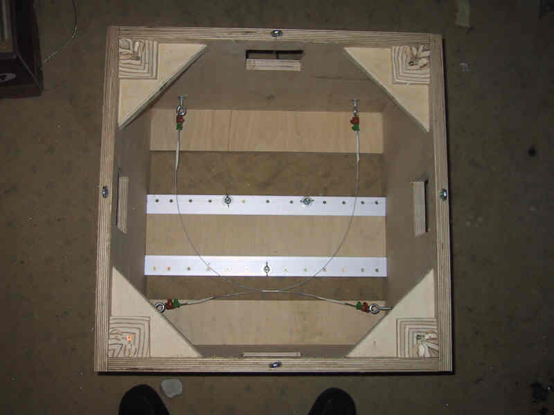
Mirror box
The mirror box is made from 20 mm birch plywood.
Outer dimensions: 54 x 54 x 42 cm
The 35 cm mirror is held by two adjustable strings which cover 90 degrees each.
So the strings fix the mirror's position in both dimensions (up/down and left/right).
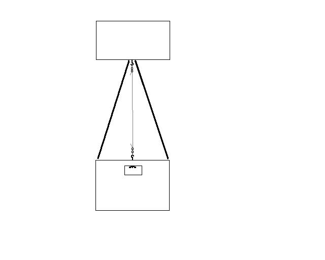
The truss triangles will be put under pressure by additional strings in the
middle of each triangle. The strings don't have to be stiff to have a stiff truss
triangle. Like in a conventional construction still both truss tubes of a triangle
contribute to the stiffness of the whole construction.
Because the truss tubes are still not delivered I have oly this drawing to shows the truss and
string assembly.
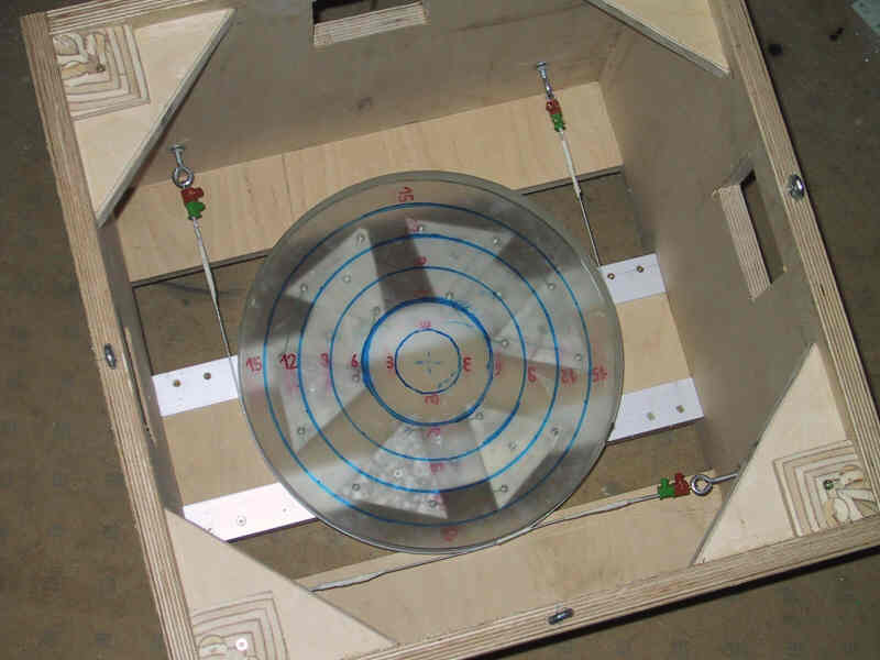
Mirror cell
For my mirror (40 mm thick) Plop calculated that a 9 point cell would
have been enough. But the calculated triangles had one corner with an
angle of nearly 180 degrees. The central support would have been near
this corner. I didn't know how to built this support without friction.
So I decided to build a cell with 18 points which is better than needed.
This cell has very simple triangle supports with M4 screws and nuts (not fixed !).
I think this little mistake still results in a far better support than a perfectly
built 9 point cell would have.
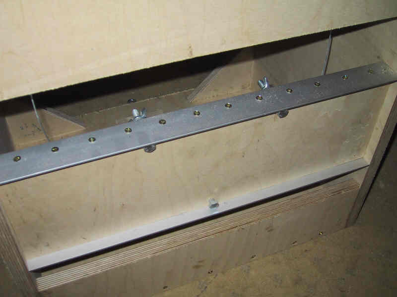
This is the bottom of the mirror cell. The plywood bar is reinforced with aluminum
angles (40x40x3mm). Three M8 collimation screws support the mirror cell.
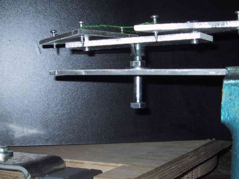
Here is one bar with trangles taken out of the mirror cell and put into a small aluminum sheet:
The collimation screw which supports the bar is partially threaded and has a nut tightened to the end of the thread.
This nut slides on a whasher which is supported by the mirror cell base. A wing nut
rests on the screws threads and supports the mirror cell bar. The bar has a slit underneath so the wing nut
doesn't turn and so moves up or down when the screw is turned to align the mirror.
The wing nut also allowes only one degree of freedom for the bar.
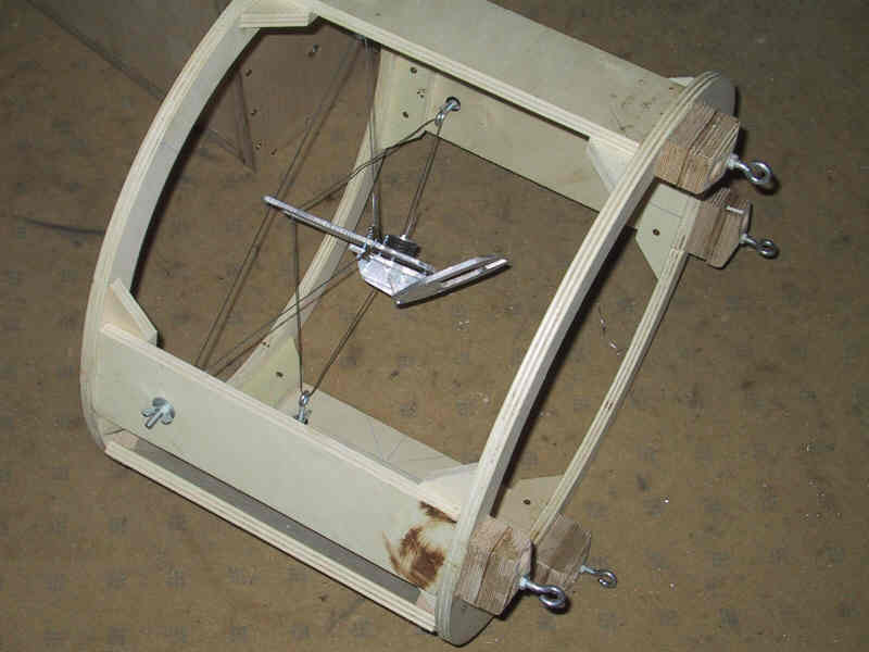
Upper ring
The upper ring is made of 12 mm plywood.
For the spider I used steel strings similar to the strings used for bicycle brakes.
The construction seems to be stiff enough because the strings are mounted off center. So they
can take more torque to prevent rotational vibrations.
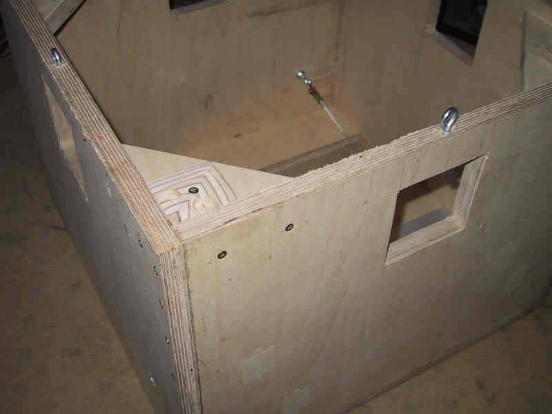
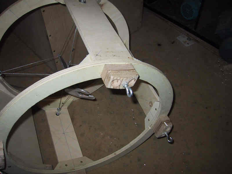
Simple truss clamps on the upper ring
The clamping of the truss tubes simply consists of holes and a hook for the string.
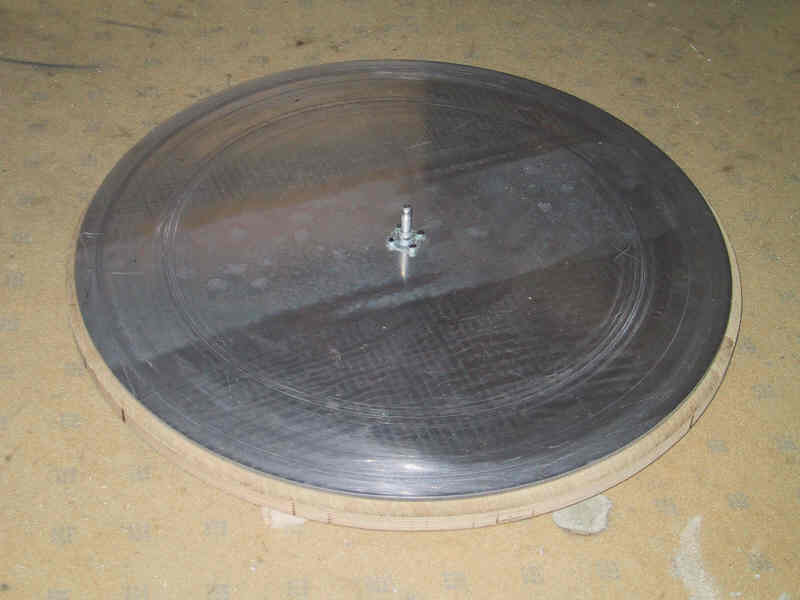
Ground board
The ground board has a toothed aluminum wheel.
The wooden plate is a little bigger than the aluminum wheel to protect
its teeth during transport. On its circumference is a step made with a router
to have some clearance for the M8 rod driving the 5 mm thick wheel.
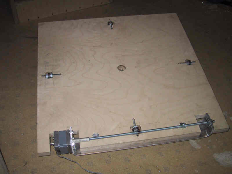
Rocker box bottom
The base board of the rocker box has four ball bearings (roller blade type)
which run on the aluminum wheel of the ground board. The stepper motor with
a M8 threaded rod drives the scope around the wheel.
I took four bearings instead of three. So there are two support points near the
altitude bearings to reduce flexing of the rocker box. Four bearings
cannot be exactly in one plane but the remaining small error (some tenth of a mm)
will adjust itself by a little flex in the ground board and rocker box base.
Later this opinion turned out as a mistake and I changed the rocker box to have only three bearings.
The driver unit with stepper motor and M8 rod can be adjusted as a whole. It makes
some pressure between worm and wheel until the rod bends a little.
This results in no play in the worm gear.
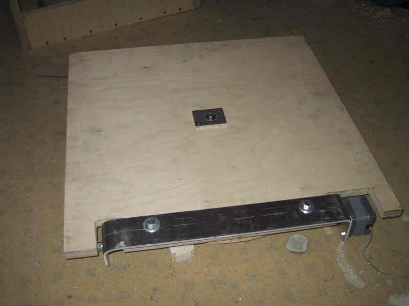
Rocker box base put onto the ground board
Now the gear is completely under the rocker box and so well protected.
The altitude supports still have to be made. Their height depends on the
center of gravity of the scope. Because the focuser and the truss tubes
are still not delivered I cannot determine this.
Altitude wheels
The wheels will rest on ball bearings and therfor have 1 mm thick aluminum
on their circumference. A toothed wheel (90 degrees sector) will
be driven by a M8 rod and a stepper motor (under construction).
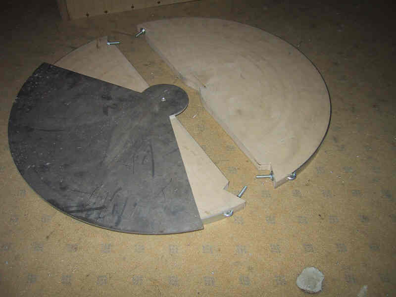
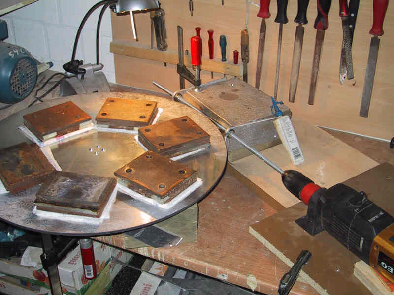
Cutting of gears with a threaded rod
This is my gear cutting assembly. The aluminum wheel is supported by
three ball bearings and has fourth bearing as a central pivot point. The
threaded rod cuts the teeth into it. The rod has a slit along its axis
so that its threads become teeth which cut into the aluminum wheel.